ENGAGEMENT EXAMPLE 04 / CCUS + OIL & GAS + INDUSTRIAL MATERIALS / INFRASTRUCTURE-LED DEMAND
Carbon capture for a multi-source industrial cluster
Prioritising capture routes and first-wave emitters when CO2 concentration, contaminants, operating profile, utilities and network specifications differ across the cluster.
SOURCE ARCHETYPES
3 stream classes
EVIDENCE SET
276 records*
ORGANISATIONS
22 profiles*
INDICATIVE TIMELINE
6 weeks*
The challenge
A European industrial cluster was preparing for access to a planned shared CO2 transport and storage network. The cluster included natural-gas-fired combined heat and power exhaust, refinery or hydrogen-plant furnace streams and cement or lime kiln exhaust. Management needed to decide which sources should enter the first development wave and which capture technologies justified pre-FEED diligence. A single technology ranking would be misleading because the streams differed in CO2 partial pressure, oxygen, moisture, SOx, NOx, particulates, temperature, flow variability and available steam, electricity, cooling and plot space.
The hardest comparison involved dilute, near-atmospheric exhaust. Post-combustion streams in roughly the 3 to 15 percent CO2 range can impose substantial gas-handling and regeneration duties, while trace contaminants can affect solvent degradation, sorbent life, membrane performance and pretreatment. Higher-concentration kiln streams may improve capture driving force but introduce different dust, acid-gas, heat-integration and process-emission considerations. Reported capture rate or energy use is not comparable unless the inlet composition, capture boundary, product purity, compression endpoint and utility assumptions are retained.
The demand horizon is moving. Regulation (EU) 2024/1735 establishes an EU objective of at least 50 million tonnes of annual operational CO2 injection capacity by 2030, and the European Commission’s industrial carbon-management strategy addresses capture, transport, utilisation and storage as a connected value chain. The research question is therefore not only which capture route appears technically capable, but which route-and-source combinations could align with network timing, CO2 specifications and realistic integration constraints.
PUBLIC CONTEXT USED TO GROUND THE RESEARCH SCENARIO
The scenario is grounded in the EU Net-Zero Industry Act and the European Commission’s industrial carbon-management strategy. The 50 Mt per year figure is a public EU injection-capacity objective, not a project forecast. The research does not determine permitting, subsidy eligibility, carbon-accounting treatment or investment viability.
Stream specification and technology scope
SOURCE ARCHETYPES
- Natural-gas CHP or turbine exhaust, approximately 3 to 5 percent CO2 under the example assumptions
- Refinery heater or hydrogen-plant furnace exhaust, approximately 8 to 12 percent CO2
- Cement or lime kiln exhaust, approximately 15 to 30 percent CO2 with process-specific contaminants
- Base load, turndown, start-stop and seasonal operating profiles captured separately
CAPTURE ROUTES SCREENED
- Conventional and advanced amine absorption
- Phase-change or water-lean solvent systems
- Temperature- or pressure-swing solid sorbents
- Membrane and membrane-solvent hybrid systems
- Calcium looping or other routes only where stream and scale evidence is relevant
COMPARABLE TECHNICAL FIELDS
- CO2 concentration and partial pressure, flow, temperature, pressure, water, oxygen, SOx, NOx and particulates
- Capture rate, product purity, recovery, steam, electricity, cooling, footprint and compression boundary
- Solvent or sorbent loss, degradation, emissions, waste, corrosion and pretreatment
- Scale, duration, host industry, capacity factor, independently reported performance and evidence date
RESEARCH BOUNDARIES
- Technical and deployment evidence mainly from 2018 to 2026, with earlier foundational evidence retained selectively
- European policy and infrastructure context with global technology evidence
- No process simulation, heat-and-material balance, cost estimate, FEED design or lifecycle assessment
- No announced project treated as operating evidence without attributable commissioning or performance information
How the research would be executed
Create the stream register
Define each source by gas composition, flow, variability, operating hours, utility availability, plot constraint and the expected CO2 transport specification. Record uncertainty ranges instead of relying on one nominal concentration.
Build a mechanism and configuration taxonomy
Separate absorption, adsorption, membranes, looping and hybrid routes. Record pretreatment, regeneration, compression and heat-integration requirements so capture technology is not assessed in isolation.
Search by stream and system boundary
Combine literature, patents, demonstration records, project disclosures, supplier data, public funding records and regulatory sources. Search specifically for contaminant tolerance, degradation, dynamic operation, emissions and long-duration performance.
Normalise only defensible comparisons
Retain original units and system boundaries. Convert energy or performance values only when inlet composition, capture rate, product pressure, utilities and included equipment are sufficiently comparable. Keep incompatible results visible but separate.
Map demonstration and ecosystem evidence
Code scale, duration, host industry, operator, developer, equipment partners, funding stage and operating status. Distinguish announced, under-construction, commissioned and performance-reported projects.
Build a source-to-route portfolio
Place technologies by stream fit, integration burden and evidence maturity. Attach sensitivity triggers, partner profiles and the site data or primary engineering questions required before pre-FEED selection.
Portfolio output
How the example output should be read
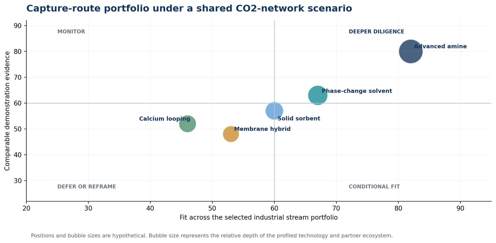
A possible synthesis could place advanced amines in deeper diligence because comparable evidence spans several post-combustion streams, while still flagging steam demand, degradation, emissions and footprint. Phase-change solvents or solid sorbents might remain conditional where modularity is attractive but long-duration evidence under the target contaminants is limited. Membrane hybrids may improve with higher feed concentration or pressure but remain weak for very dilute atmospheric exhaust without compression or staging.
The output would also prioritise emitters. A first wave could favour a stable kiln or furnace source with available heat integration and manageable pretreatment. A dilute CHP source could be monitored or deferred until network timing, energy supply and operating profile improve. Each position would retain its stream assumptions so the portfolio can be updated when the network or plant boundary changes.
Deliverables and indicative schedule
DELIVERY PACKAGE
- Excel evidence base with approximately 276 screened records and full stream, boundary and maturity coding
- Source-to-route portfolio with assumption, sensitivity and confidence fields
- Approximately 22 developer, project, equipment and integration-partner profiles
- PowerPoint decision narrative with first-wave options, integration dependencies and pre-FEED questions
SIX-WEEK WORKPLAN
- Week 1: source register, system boundaries and decision criteria
- Weeks 2 and 3: technical, project and patent evidence screening
- Week 4: normalisation, demonstration coding and partner profiling
- Week 5: portfolio construction and sensitivity review
- Week 6: quality checks, evidence database and decision presentation
Note: The six-week schedule is a planning assumption. Actual timing depends on the number of source streams, system-boundary complexity, source accessibility, geographic coverage, evidence quality and the depth of project or developer profiling required.
WEBSITE PRESENTATION SUGGESTION
Use a filterable stream-to-technology portfolio. Visitors adjust CO2 concentration, contaminants, operating profile and utility constraints, then see route positions and evidence gaps change. A fixed drawer explains the assumptions behind every score, keeping the stream specification central to the interaction.
Let's discuss your project
If your team is prioritising capture routes across multiple industrial sources or preparing for a shared CO2 network, August Research can structure the landscape around the stream conditions, infrastructure boundary and evidence needed for the next investment gate.
Note: This illustrative engagement is a hypothetical website example, not a client project or actual finding. All counts, profiles, scores, findings, timelines and deliverables would change with the scope and available evidence. Secondary research does not replace regulatory, engineering, laboratory or operational validation.